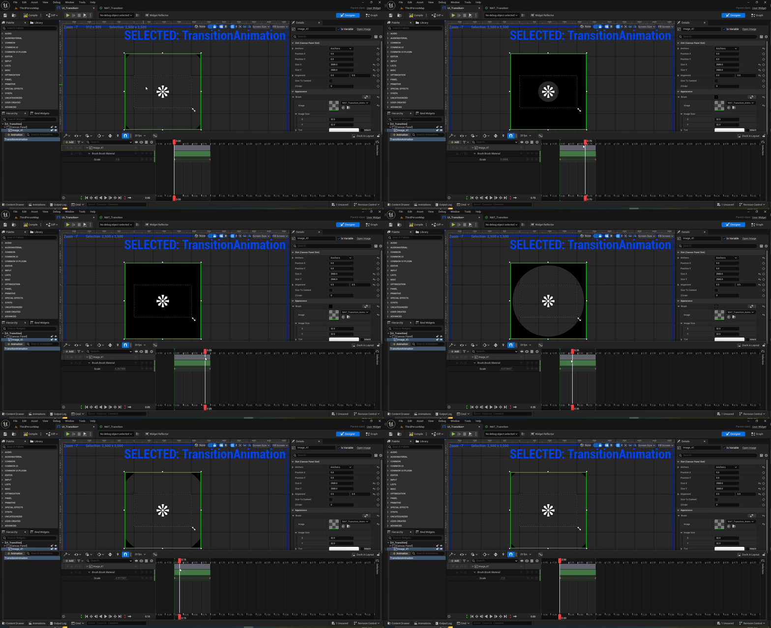
Replicating Cropout's Transition Animation
 If you are an Unreal Engine developer, then you may be familiar with the Cropout sample project. This project has a lot to offer when it comes to the Engine’s capabilities and I have started a personal journey to reverse engineer it to see how I can enhance my own projects.
Cropout features a screen transition animation that I like and I also thought it would be a great starting point to learn from, so this post is about how I replicated the transition from scratch.
Setting Up the Transition UI in UMG
I will create a Widget Blueprint and name it UI_Transition.
After the widget has been created, I will add a Canvas Panel and then an Image as a child of the Canvas Panel.
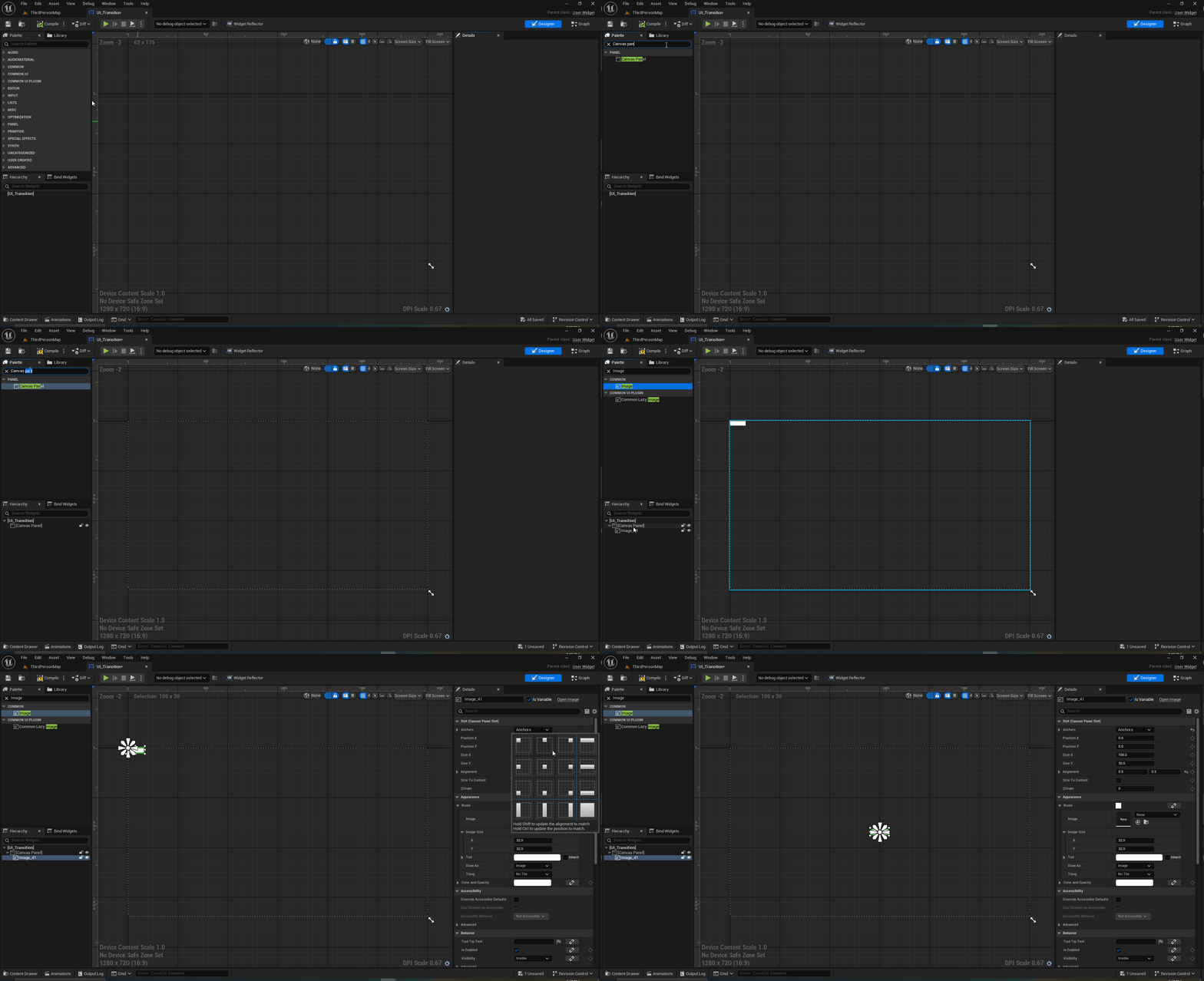
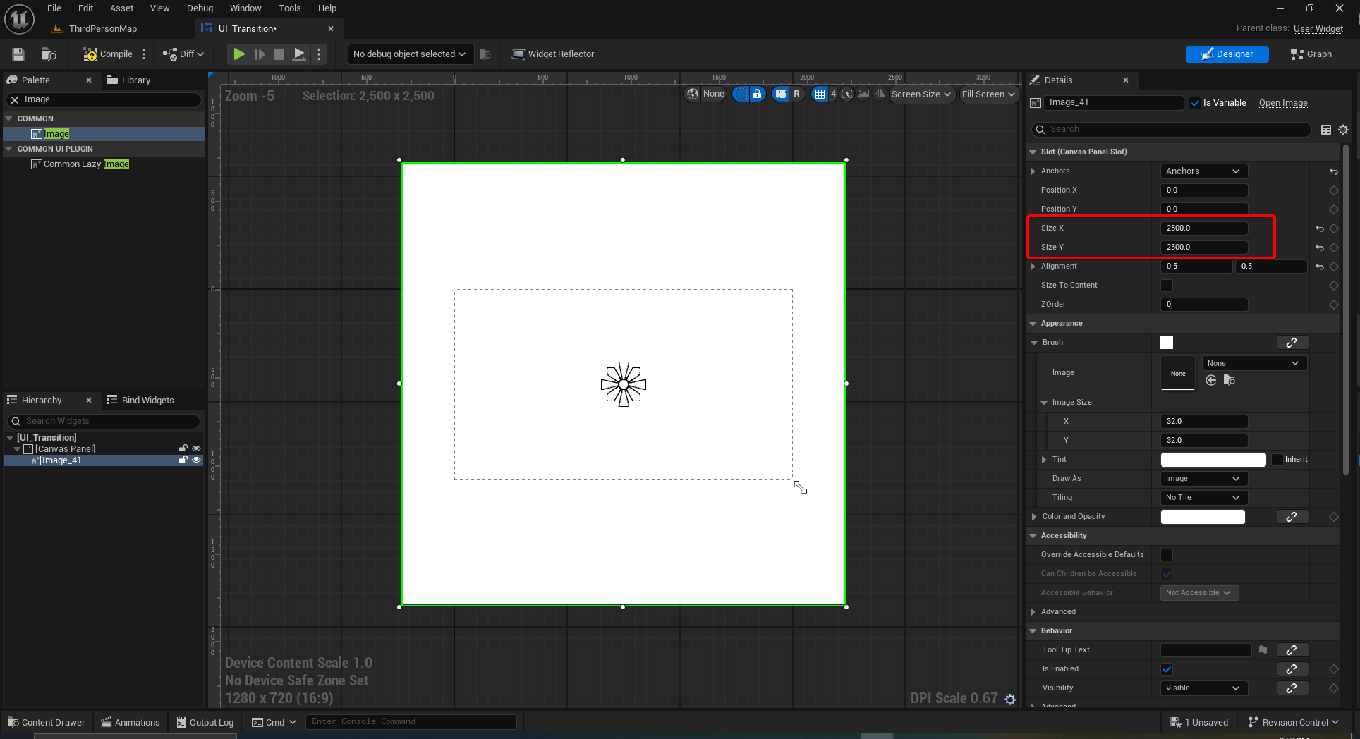
Select the image, make sure it is centered on the canvas panel and set its Size X and Size Y to 2500.
Creating the UI Transition Material
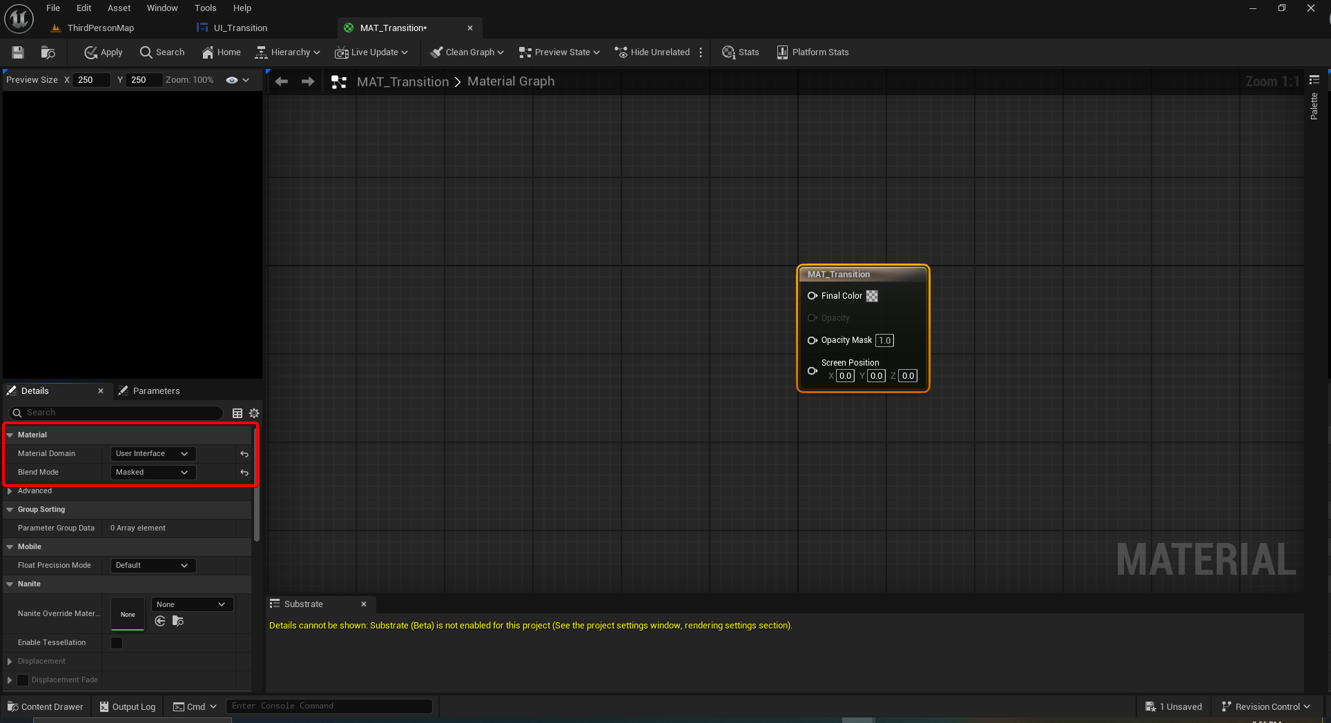
Let’s create a Material, then set its domain as User Interface and its Blend Mode as Masked.
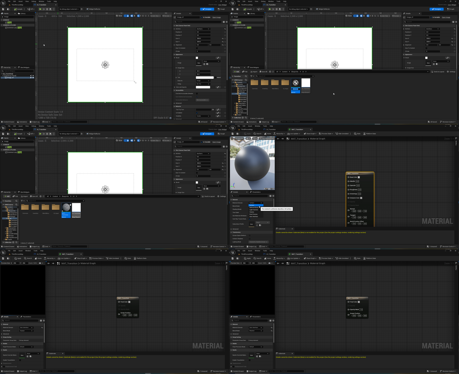
The initial material should look like this.
Texture Coordinate Node
In the Material Graph, right click and look for the Texture Coordinate Node and select it.
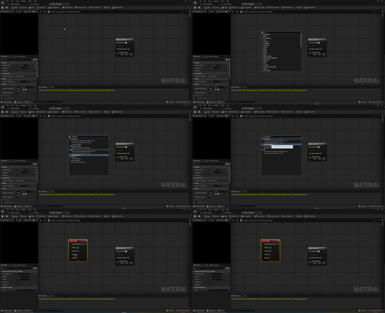
This node will give us initial UV coordinates. It allows to increase tiling or mirror UVs, it is sometimes used to map textures on to a mesh directly in the engine, but I will be using it with a different purpose.
Constant Bias Scale Node
In the Material Graph, right click and now look for the ConstantBiasScale node and add it to the graph. Set the Bias to -0.5 and Scale to 2.0.
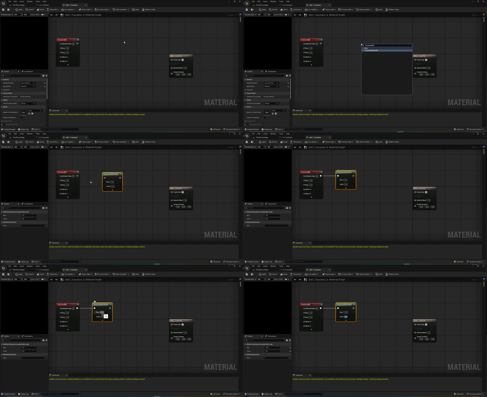
What we are doing in here is remapping the UV Coordinates from (0,0) to (-1, 1). What this means now is that the coordinates (0,0) are now at the center of the UV map. This will come handy in a few moments.
Distance Node
Following the usual procedure, now add the Distance node to the Material Graph and connect the output of ConstantBiasScale node to the A input of Distance.
Add a constant node and assign its value to zero and plug it to the B input of Distance.
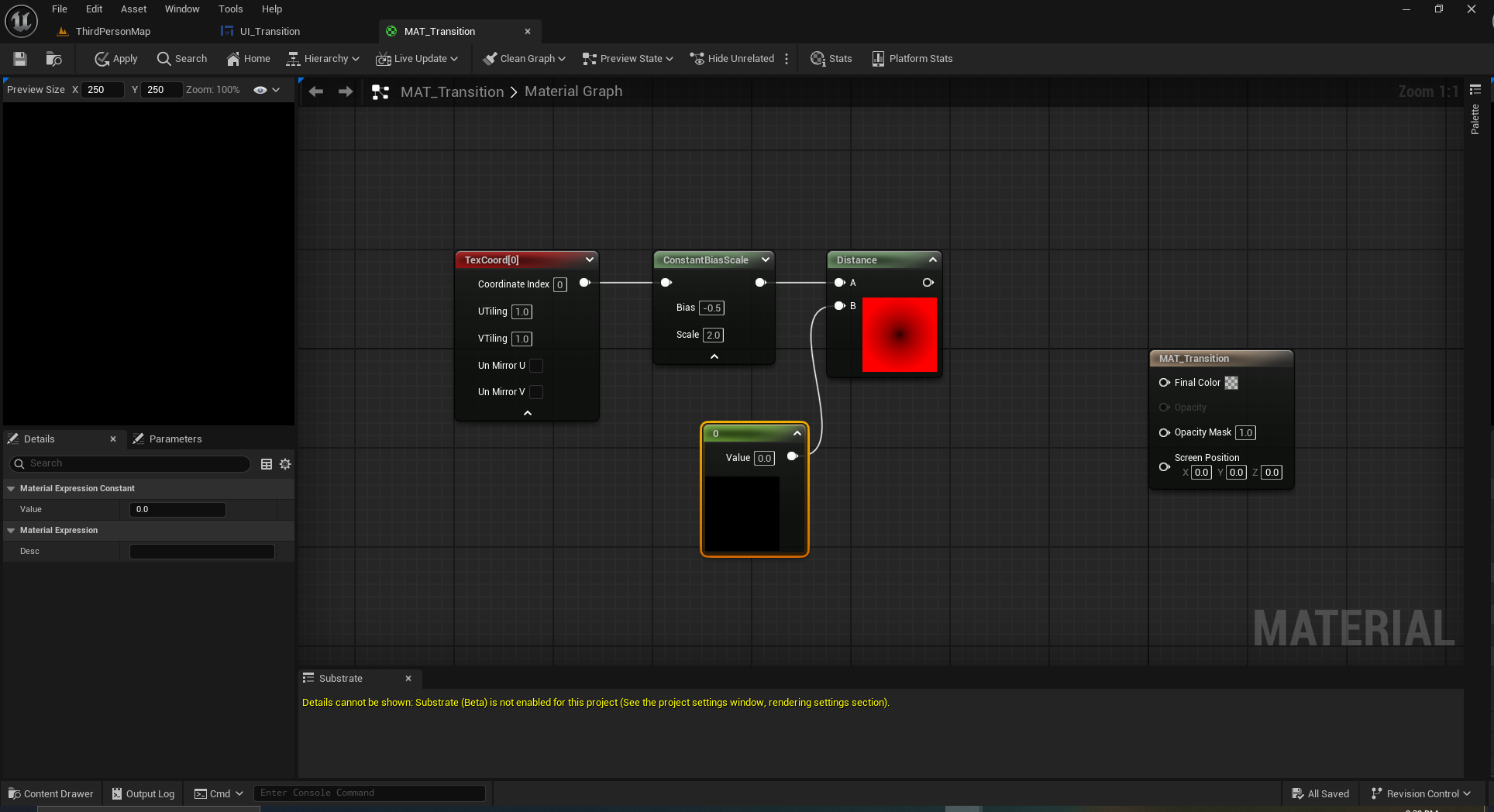
With this operation we are calculating the distance from the center of the texture to whatever point is coming out from ConstantBiasScale, which produces the gradient you see in red. The reason the texture is red is because it is using the U values from the Texture Coordinate and UVW coordinates are equivalent to RGB values in color space.
Finalizing the Material
Create a Constant node, set its value to something like 0.416, right click on it and convert it to a parameter. Finally call it Scale.
Insert the Add node into the material graph and plug the result from Distance into Add’s A input and the Scale to input B.
Plug the result from Add into the Material’s Opacity Mask and create another constant, keep it as zero and plug it to the Material’s Final Color.
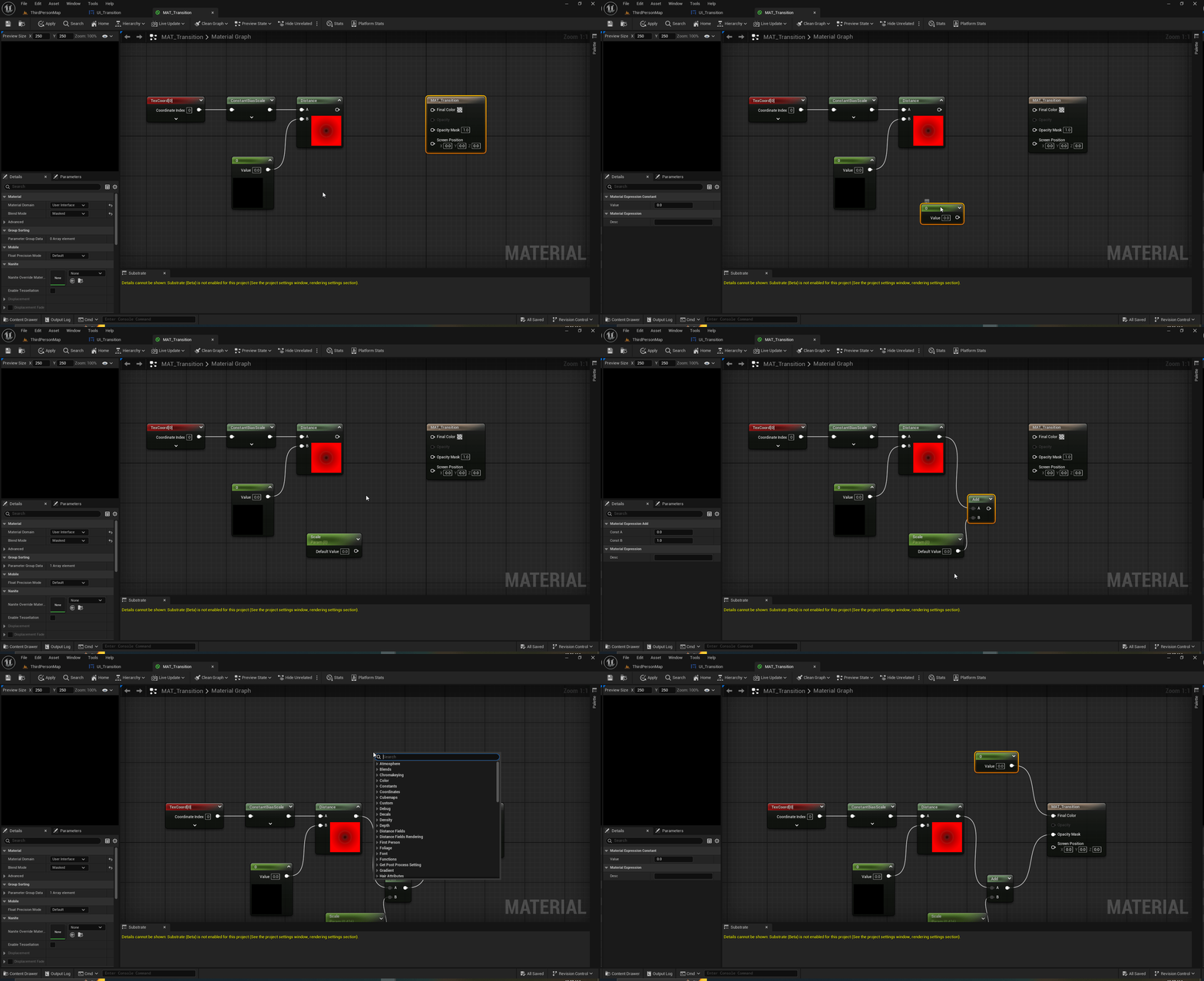
Adding the Material to the Widget Blueprint
Open again the UI Transition Widget Blueprint. Select the image and add the material to it.
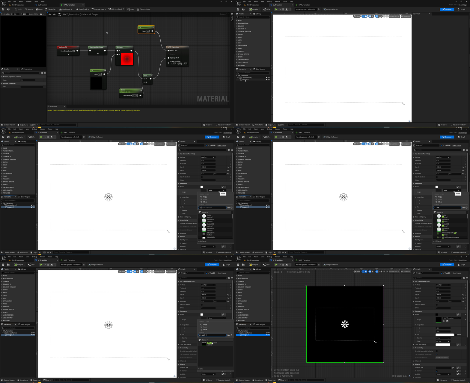
But to see the effect in action, we need to apply an animation to the material we just added. Here is where the Scale parameter we created will be useful.
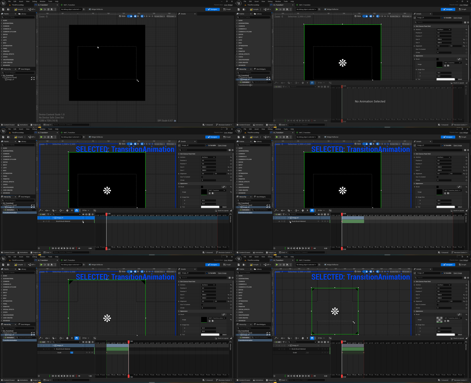
And finally this is the result.
